RESEARCH

Thermal Refrigeration Based Projects


1. Fabrication of thermo-electric solar air conditioner
2. Water Cooler [censored] Air Conditioner
3. Fabrication of thermo-electric refrigerator
4. Transformer heat reduction system
5. Fabrication of furnace using infrared Lamp
6. Water cooler [censored] Water heater by using refrigeration System
7. Remote controlled boiler flame adjustment system
8. Fabrication of Automatic temperature controller with cooling system
9. Fabrication of Hot and Cold Water Dispenser
10. Fabrication of Solar air conditioning Machine
11. Waste chill recovery heat exchanger
12. Fabrication of Solar Air Conditioner
13. Fabrication of Mist Coolant system
14. Automatic Electro-plating coating process
15. Fabrication of Solar Water Heater by using parabolic collector
16. Electrical Power Generation using Thermal Power Plant
17. Fabrication of Solar refrigeration system
18. Fabrication of Bottle Cooler
19. Fabrication of Solar Fridge
20. Fabrication of Solar Kettle (or) Solar Parabolic Collector
21. Fabrication of Solar Air Cooler
22. Fabrication of Activated Carbon Manufacturing Plant
23. Fabrication of Mini Water Heater
24. Automatic pneumatic vulcanizing Machine using heat sensor
25. Solar Water Purification by using thermal method
26. Fabrication of Paper cup folding Machine
27. Fabrication of Ground Dryer
28. Fabrication of Micro Wave Oven
29. Fabrication of Miniature Boiler
30. Fabrication of Solar Air Dryer
31. Fabrication of Lube oil cooler
32. Fabrication of double effecting solar cooker
33. Fabrication of Solar Air Cooler [censored] Heater
34. Fabrication of refrigeration system (trainer)
35. Fabrication of L.L.D.P. Material extruder
36. Fabrication of solar Water Heater
37. Fabrication of double reflection solar Cooker
38. Fabrication of Cooling tower
39. Electrical Power Generation using Steam Power Plant
40. Fabrication of Solar Water Disalation (Purification) by using parabolic method
41. Multi-Purpose Ground Dryer (or) Multi-Purpose Dryer and Room Heater
42. D & F of Chemical Processing Plant
43. Fabrication of solar water disalation by using photovoltaic method
44. Fabrication of automatic humidification system

BUET ME'03 Batch Project Ideas

1.Automatic Weight Sensing Sliding Door (click here to download)

BUET ME'06 Batch Project Ideas

No Data Available

BUET ME'04 Batch Project Ideas

These Projects Ideas Were Prososed By ME'o4 Batch of BUET :

1. Robotic Ball Throwing Arm (click here to download)

BUET ME'05 Batch Project Ideas

These Awesome Project Ideas were submited by ME'05 batch of buet :

1. Scissor Lift
2. Programmable Pilot Static Tube Traversion Mechanism
3. Digital Anemometer
( Team Members:
1. Anjan Goswami 0510126
2. Jawad Al Ratun 0510110
3. S.M. Rezaul Haque 0510118
4. Islam Md. Rizwanul Fattah 0510115 )
4. Automatic Titrator
5. The Amphibian Car
( Team Members:
1. Adip Al Quraishi 0510002
2. Mahmud Adnan 0510011
3. Hasib Ibne Rahman 0510021
4. MD. Zahabul Islam 0510030 )
6. Climbing Robot
7. Trackerbot 1.0
8. Autometic Gas Oven
( Team Members:
1. Rony 0510043
2. Shahadat 0510052
3. Bappa 0510061
4. Pavel 0510070 )
9. Terrain Hazard Optimised Robot
( Team Members:
1. Atunu 0510005
2. Rokan 0510014
3. Prajna 0510024
4. Nahid 0510033 )
10. Autometic Butterfly Valbe Control
11. Spy Robot
12. Robotic Vecuam Cleaner
13. Mechanised Intelligent Spray Painter
14. Autometed Secured Garage Door
15. Scrap Metal Carrier
16. Autonomous Lettering Device
17. Driver Free Electric Train With Autometic Door System
18. A Crane Of Two Arms
19. Autoneted Spot Welder
20. Mini Gripper and Mover
21. Dual Surfaced Mechanical Billboard With Automated Luminosity Control
(click here to download)
22. Autometic Painter Bot
( Team Members:
1. Anjan Goswami 0510057
2. Jawad Al Ratun 0510039
3. S.M. Rezaul Haque 0510048
4. Islam Md. Rizwanul Fattah 0510066 )

Check The Image Gallery For Images:


Image
Gallery

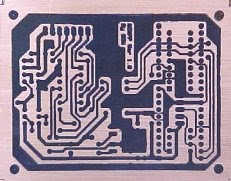
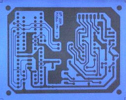
Making PCB at Home (Final)

Drilling
Drilling with 0.8mm drill bits can be a bit tricky as it's easy to break the drill bits. Always hold the drill straight and do not bend it when the hole has started. Putting a soft block of wood under the PCB provides a good base to drill into. Once you have become experienced at drilling I would recommend using Tungsten Carbide drills (FE49D) which easily break but last much longer.
1. Dry off the board and clean away the blue etch resist with PCB solvent cleaner
2. Using a 0.8mm PCB drill bit drill out all of the component holes
3. Some 1mm holes may need to be made for connectors, 3mm for corner fixings
4. Finally use a PCB rubber to clean the copper ready for soldering
So now your PCB's finished and you can start soldering the components in. You should do this soon after you have cleaned the PCB (within 1 hour) as the copper soon oxidises and becomes hard to solder onto.
Get Full Bangla Instructions

Making PCB at Home (3)

The Etching


Now for the messy bit, etching the PCB to remove the unwanted Copper. Please read the warning at the top of the page as it is important to take appropriate precautions before handling the etch chemicals. I recommend you do this outside or in a shed and you must ware glasses and gloves. Keeping the etch chemicals warm (45deg C) is essential as it reduces the etch time from over an hour to about 15mins.

1. Dilute the concentrated Ferric Chloride fluid with water (1:1) and pour into the one letre glass jar and screw the top on

3. Place a sheet of news paper on a flat surface and put the trays on this

2. Fill the kettle with water and boil

3. Heat the Ferric Chloride jar in a bucket of hot water. Caution don't spill any drops and keep away from food


1. Pour 1cm of boiling water into the bottom tray then place the other tray on top
2. Put the PCB copper side up on the top tray and pour all the Ferric Chloride on top
3. Gently rock the top tray to keep the etch fluid moving avoiding spillage
4. After about 15mins all of the unwanted Copper should have disappeared
5. Remove the board and drop it into a bucket of cold water to clean off
Usefull tip: For small boards just drill a 1mm hole in the corner of the board and tie 2ft of strong cotton to this. Now put the board straight into the Ferric Chloride jar with the end of the cotton outside and put the top on the jar. Keep the jar hot by heating in a tray of boiling water and gently rock to keep the etch fluid moving. Every 5mins use the cotton to lift the board out and check progress. This method is much less messy as the Ferric Chloride is always left in the glass jar.

Making PCB at Home (2)


The Artwork


Until recently the artwork had been an area of DIY PCB manufacture which caused the biggest problems. But now by combining high quality laser printing with the Press-n-Peel PCB transfer system these problems have been solved. The first stage is to transfer the circuit layout from the PC to the special Press-n-Peel film. You will find that my projects provide Laser print files (.prn) for printing the circuit layout direct onto this film.

1. I cut the Press-n-Peel film in half for small boards so it lasts longer

2. Put the film in the laser printer so that the print will appear on matt blue side

3. At a DOS command prompt type: copy filename.prn lpt1 to print onto the film

This will produce a contact print where the black image will end up as Copper on the final PCB. Now to transfer the artwork to the Copper board by following the instructions with the Press-n-Peel film.


1. Clean the Copper board very well with the PCB cleaning rubber
2. Heat the cloths iron to 300 deg.F (Acrylic to Polyester setting)
3. Hold the film with the print in contact to the Copper and smoothly iron the film down until the print appears black through the film (about 1min)
4. Allow 5mins to cool down (or speed this up with water) then peel the film off
This should produce a clean black print onto the Copper. If you let the film move or overheat then you will find that the tracks and writing will be smeared and out of focus also the film may be wrinkled up. If you don't use enough heat or heat unevenly then the film may not stick or be dark enough. In either case clean off the PCB and try again, you should get it right after a couple of goes.

Making PCB at Home (1)

One of the most discouraging things about making a hardware project (apart from obtaining all of the components) is building the printed circuit board - PCB. It is sometimes possible to use strip board or some other pre-fabricated board but more often than not the circuit complexity and performance requires a proper PCB to be made. The good news is that due to improvements in printing and processing technologies it is now relatively easy to make inexpensive high quality PCB's at home.
WARNING: Making PCB's requires the use of Ferric Chloride (FeCI3) which is corrosive so avoid skin and eye contact. Remember safety first use glasses, gloves and protective overalls. Ferric Chloride is also very good at distorting cloths weeks after you think you have washed it off. If you do get any on your skin then wash it off immediately with lots of water and soap.
The Shopping List

This is the minimum things you will need:
1. Access to a PC with a Laser printer eg: HP Laser Jet
2. Cloths iron
3. Kettle
4. Water bucket
5. A one litre glash jar with plastic screw top (biscuit jar)
6. PCB hand drill with 0.8mm and 1mm drill bits - FR84F, QY64U
7. Copper-Clad fiberglass board - WF40T
8. Press-n-Peel PCB transfer system - AB15R
9. Ferric Chloride Copper etching fluid 250ml - WF10L
10. Two plastic etching trays (ideally different sizes) - CH38R
11. PCB cleaning rubber - HX04E
12. PCB solvent cleaner - LL59P
13. Safety glasses, latex gloves, old clothes/overalls - KE83E, YJ84C

Microcontroller overview (Final)

Designing a Circuit


First, Think of what inputs and outputs your circuit will have: switches, sensors,lights, motors, etc. Then you can determine the power requirements. For simplicity, our circuit uses batteries, but a wallwart with a voltage regulator is more reliable.


Next, determine how your inputs will interface with the microcontroller.Some pins take only digital inputs. The general rule for this is that powerbrings the voltage up and ground draws it down. To make a button that changesan input pin from 0 to 1.


Some micro pins take analog as well as digital inputs; you can feed these fromanalog sensors that produce a range of electrical values. For example, a potentiometer'sknob changes its resistance, which changes a voltage fed through it. Connect a pot to a pinthat works as a ADC converter and the micro will convert the current position of the knob into a number you can program with.

An LEd will light up directly from a micro's output pins, but things like motors need more current. You can supply this by connecting an output pin tothe base of a transistor that has a higher current runing through it. Motors may generatevoltage spikes that can damage your chip, but a diode running in reverse across the transistorwill protect the circuit.
Once you know which sensors connect to which types of pins, you need to study your microcontroller's datasheet.As with most micros, pins on the PIC12F675 perform multiple tasks, and you set resisters in your software to tellthe pins how to behave in the resisters table from the PIC12F675 datasheet on Microchip's website.